Saturday, October 24, 2015

Week 5


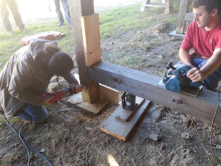
Week 5. This week has been filled with projects that focus on clean up and organization. We took down the floor system we completed in week 4. Then we moved into the project you can see in the picture above. We were replacing the bottom section of the posts in the lumber storage area with pressure treated wood and a moisture barrier. (The original ends of the posts were beginning to decompose, from the water wicking up the wood.). All of this is being done in preparation for placing a new concrete pad.


This is the area we're working in. 


The newly cut bottoms for our posts. I'm sticking the adhesive water barrier to the top of the new post, which will prevent water moving up the post through capillary action. The bottom section of the posts will be footed in the new concrete pad. Concrete has a very low dew point, which makes it easy for moisture to condense on it's surface. That, combined with bulk water management is what we're trying to combat.


The jack holding the vertical beam up while we replace the post footing. 


In this picture you can see the board in front of the missing post, that says 'SAVE' on it. We screwed this board, level to the post on both sides. Using it's straight edge as a guide, I ran the skill saw through the beam (both sides). The skill saw isn't able to fully penetrate the beam, so I finished the cut with the sawzall. (Top picture)


After replacing the bottom of the beam with the new pressure treated wood, plates were screwed in place over the old and new ends, to keep things from shifting.


With the posts being finished, we primarily focused on getting the form boards cut to their appropriate lengths and then placed at the correct depth/height. This will ensure that the concrete, when placed, can be leveled off without issue. The notches cut in the form boards sit over the concrete footings that are already in place beneath the existing posts. Dirt was then backfilled around the boards, ensuring that concrete will not leak out or break them.


Trenches being dug, and form boards placed over footings.


The other project I worked on this week was sealing the (pressure relief?) cracks in the concrete of another foundation. Using a special caulk, we filled the cracks and putty knived it smooth. This will keep water and debris from wearing at the foundation internally. (Before we used the caulking, we used an air compressor to blow the bits and pieces of debris that had already ended up in there. Definitely a moment to be wearing safety glasses... or perhaps a full face shield.)


Finishing the caulking job with a putty knife. 


Monday, October 19, 2015

Week 4


Week 4!! Starting where we left off last week with our stairwell opening, in our floor framing exercise. Here we're starting to add full length joists. All of our joists are put in place to support the sub floor and finished floor. The tail joists also support the sub and finished floor system. The headers keep the opening spanned the correct distance, preventing it from shifting inwards, while the joists (full length) that frame the opening keep it from shifting outwards.


This is our floor layout with all of the joists, and stair opening components in place. In this picture you can also see our 2 1/2" partition. The partition supports a load bearing wall and must be reinforced with blocking to sustain itself under the anticipated weight. We used 4 blocks, measuring 7 1/4" (the same as the width of the joists, so the blocking will span the full width of the joist. This is for even dispersal of pressure.) The length of the block is 2 1/2", which is required to span the distance between the partition joists.


After we finished our floor framing, we moved onto our ledger. The ledger is required to support the joists of the stairwell opening. Much like the partition opening, these joists require extra reinforcement because of the extra anticipated load they will have to bear. The ledger is 2 1/2" x 2 1/2", and must span beyond the stairwell opening, to just beyond the joists that make up the partition (?). The ledger is nailed in place, under each joist it supports, with three 16d nails. The nails cannot sit in the same plane (if you look at the picture above, you will see that the nails form a sort of triangle), because they will split the narrow ledger. Even with blunted ends, they must be placed in staggered increments - but still directly underneath each joist, so that the joist will have the maximum amount of support.


The picture above depicts the nailing schedule for the double joists that frame the stairwell opening. Instead of three 16d nails, we use five here. Again they are placed in staggered increments, directly underneath each joist for maximum support.


Even though this picture depicts the total progress we made for the week, I wanted to show the bracing and explain the importance of squaring. Before we started any work on the blocking or skids (but after the joists were laid), we measured the length and width of the shed, than the diagonals. We go through this process to check how square the floor system is, before everything (especially pressure treated lumber, which is comparably expensive ) is laid and fastened in place. Our diagonals happened to be off by about 3/4" - 1/2". We had one person stand on the corner which measured long diagonally, and on the opposite corner of that same long diagonal, I took a sledge hammer and a piece of scrap wood (to soften the blow) and gave it a few whacks until our diagonals were equal. Our foundation was officially square, so we braced it off with some extra 'smart siding', and flipped the floor system over so that we could move onto blocking and skids.


Towards the end of this week we were experiencing some uncooperative weather, so we changed things up and moved inside to continue working on our sheds. The shed I primarily have worked on during this past week was the 12' x 10'. We put the floor framing together in pretty quick order, but had to finish out our blocking. Before we could put the skids on the shed (which will allow the shed to be delivered without causing any damage to the bottom), the blocking must be put in place. Each block measured roughly 14 1/2" x 7 1/4", and were placed in every other bay, starting with the second bay in. We placed the last two in the second to last bay.


This last picture depicts the notched bottom ends of the skids. These are done at a 45 degree angle, and help prevent the skids from getting hung up or stuck on anything while loading or off loading from the trailer.


I know this picture doesn't have much to do with BCT, other than I found our little friend on my tool belt when we came back from break!


Thursday, October 15, 2015

Week 3


So here we are in week 3! We've moved onto placing sill plates. They had been cut to measurement (by the previous group who were rotated out as we were brought in.), to sit along the chalked foundation line... or so we thought. We started out measuring the placement of the anchor bolts, and their relative placement on the sill plates. The anchor bolts were dropped too deep in the concrete, so we attempted to compensate by drilling recessed holes. Unfortunately this did not work out, there was too little material left in the sill to secure the bolt with the washer and nut.


In the above picture we are checking the alignment of the plates, with the chalked foundation line. We were having some issues with too many snapped lines, and ended up remeasuring the squareness of the foundation and snapping a new line. We were fortunate, in that we had minimal waste and only had to junk one board. 


Here we're cutting a new sill plate to replace the junked original. 5 1/2" width, and length measured to makeup the remaining gap.


As I mentioned earlier, the anchor bolts were originally recessed too deeply. Here we're drilling through the sill plate, and the concrete foundation to place a whole new bolt. With the new bolts holding our sills in place, there will be less concern over the structures integrity. 


The newly drilled hole. Lots of concrete dust. 


Here we jump around a little. We were all asked to work together on the group floor framing exercise. The joist and stairwell openings were laid out previously, so we took measurements for each joist, and checked the stringline along the outside of the box sill. The line is strung as a reference for the box sill and joists. If the joists are too long or short, it can push the box sill out or pull it in, moving it out of alignment. In the picture above, you can see our stairwell opening, headers, tail joists and girder. The openings in a floor layout should always be done first, before any other joists are laid. 


A closeup of our inside header, outside header, tail joists and full length joists that frame the stairwell opening. If you look very closely, you can see the orange stringline on the outside of the box sill.

Saturday, October 3, 2015

Week 2


Couple additions to our batter board setups here. We used a straight edge board with a 4' level attached to it, to determine which batter boards needed to be raised/lowered. There was a lot of improvising and creative brainpower on site this week.


Our kerf mark to the left designates the original foundation dimension. We then measured 4" to the right to determine the foundations footing dimension. (Please ignore the kerf mark to the right. The 4" footing location on the batter board should have been designated by the placement of a nail. This was rectified and the foundation line was then moved so we could begin setting up our concrete forms.)


String lines moved 4" from their original kerf mark to the placed nail head. Represents the outside of footing.


Beginning to setup the forms. In the photo above you can see the alignment of the footing line with the inside of the form board. Just to the outside of the boards, we've braced the two seperate boards with a (). This will keep the form strong enough to withstand the pressure of the concrete, once poured.


In this last photo here, we are plumbing the form board to the footing line. This is the best opportunity to get a straight and true foundation. We've also driven stakes (just right of the form board and level). These will also help brace the form, keeping it in place as the concrete is placed.
 
 
Picture of full layout, all batter boards are raised. All string lines have been strung and moved outwards 4". the setup is now ready for actual form work.
 

Week 1


     Our first week working outside of the shop, we drove ourselves down over the hill and were seperated into small groups - ours being a group of three. We were asked to set up lines for a squared foundation (eventually moving into erecting concrete forms), and in the picture above I am driving one of the four stakes.
 

Driving our third stake.


Here we are fine tuning our foundation's squareness, shifting the nail head as needed (and maybe driving another stake or two.). Once we were getting matching lengths, widths and diagonals, our foundation was square and ready for us to tie our lines on.
 

Stringing our line, making sure it's wrapped tightly and securely.


Once we had a square foundation to work off of, we started to construct our batter boards. They needed to be set at a 90° angle, so we went ahead and used a 3, 4, 5 triangle. If measured 3 feet on one leg, 4' on the other, the span between them pulled in (or pushed out) to 5' gave us our right angle on each of the four batter boards. 


Finally our batter boards get their legs! We measured 3' from our stake and line to get each batter board leg equidistant and keep each leg parallel to the foundation line. Next post we show how we set up for our foundation footing.